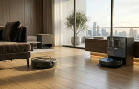
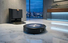
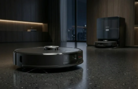
Top AI Robot Vacuums 2026: Roborock vs Roomba Combo Review
Discover the top AI-powered robot vacuums of 2026. Read our expert comparison of the Roborock Saros and Roomba Max 705 Combo to find the best smart cleaner for your home.


 by Simo Naboussi
 Welcome to the precipice of creation. If you are reading this, you are likely not looking for a superficial overview of what a robot is. You are looking for the "how" and the "why" that separates a pile of servos from a machine that perceives, decides, and acts. Robotics design and engineering is the grand unification of the physical and digital worlds. It is the discipline where the elegance of mechanical kinematics meets the deterministic rigor of real-time software, and where the chaotic noise of the real world is tamed by the mathematical beauty of sensor fusion.
As senior engineers, we understand that a robot is a system of systems. It is a fragile equilibrium of constraints. You want high torque? You add weight. You add weight? You lose speed and battery life. You want advanced AI perception? You increase compute latency and thermal load. The "art" of robotics lies not in maximizing one metric, but in navigating the trade-offs to solve a specific problem within the bounds of physics and economics.
We are currently standing in a "Golden Age" of robotics. The barriers to entry—access to high-performance actuators, compute, and open-source software—have never been lower, yet the ceiling for complexity has never been higher. We are moving away from the blind repetition of industrial arms in cages toward autonomous, collaborative systems that work alongside humans in unstructured environments. We are seeing a shift from rigid, heavy machines to soft, compliant organisms made of silicone and fabric. We are witnessing the migration from centralized control to distributed, fault-tolerant architectures like ROS2.
This report is an exhaustive exploration of the modern robotics stack. We will dissect the engineering design process, exploring why "solutioneering" is the enemy of innovation. We will delve into the physics of ground loops—the silent killer of sensor data—and the chemistry of LiFePO4 batteries that power our logistics fleets. We will compare the deterministic latency of FPGAs against the raw throughput of GPUs. We will unpack the "dark arts" of PID tuning and the mathematical gymnastics of singularity avoidance. And we will face the ethical weight of our creations, guided by ISO standards and a responsibility to the humans who will work beside them.
The graveyard of failed robotics startups is filled with companies that built incredible technology for problems that didn't exist. In robotics design and engineering, the most critical step happens before a single line of code is written or a single bracket is machined: defining the problem.
Experienced engineers guard vigilantly against "solutioneering"—the tendency to fall in love with a specific solution (e.g., "I want to use a hexapod chassis" or "I want to use this specific 3D LiDAR") and then search for a problem that fits it. This backward approach almost invariably leads to products that are over-engineered, too expensive, or functionally useless. The engineering design process must be rooted in a "problem-first" mindset. It starts with the "Ask" or "Define" phase, where we strip away our assumptions and rigorously interrogate the requirements.
For instance, if the challenge is to "move a box from point A to point B," a junior engineer might immediately envision a bipedal humanoid carrying the box. A senior engineer, however, will ask: How heavy is the box? Is the floor flat? Is there a human in the way? Often, the best robot for the job is a simple conveyor belt or a wheeled cart. The design process is about filtering the infinite solution space down to the feasible solution space.
The standard engineering design loop is a recursive fractal. We cycle through these steps at the macro level (the whole robot) and the micro level (a single joint).
A common pitfall identified in robotics manufacturing is the lack of Design for Manufacturability (DFM) in the early stages. A prototype that works perfectly in the lab might be impossible to mass-produce. For example, using hobby-grade servos or 3D-printed parts that cannot be injection molded will kill a product when it tries to scale.
Scalability must be a core requirement from day one. Using "non-commercial grade components" or parts with long lead times can result in supply chain bottlenecks that strangle a company just as it starts to grow. Senior engineers know that "custom" is a dirty word. We strive to use Commercial Off-The-Shelf (COTS) components wherever possible to reduce risk and cost. If you are designing a custom gearbox when a standard planetary gear would suffice, you are likely making a strategic error unless that gearbox is your core IP.
Robotics is inherently multidisciplinary. The mechanical engineer needs to know where the cables go; the electrical engineer needs to know the motor current draw; the software engineer needs the kinematic model. Inadequate documentation is a major cause of failure. The "Ask" phase never truly ends; it just shifts from asking the customer to asking the team. Cross-disciplinary communication is often cited as an underrated skill; you must be able to explain to a software developer why the mechanical backlash prevents their PID loop from stabilizing.
The physical form of the robot dictates the upper limit of its performance. No amount of control theory can fix a robot that is mechanically incapable of reaching its target.
At the heart of robotic manipulation is kinematics—the study of motion without regard to the forces that cause it.
Every robotics engineer eventually encounters the kinematic singularity. A singularity is a specific pose where the robot loses its ability to move in a certain direction.
Imagine a standard 6-axis industrial arm fully extended to reach an apple. At maximum extension, it cannot move "forward" any further. If the controller commands it to move forward at 1 meter per second, the math (Inverse Kinematics) might calculate that the joints need to rotate at infinite speed to achieve that impossible motion. This results in the robot locking up, vibrating violently, or triggering an over-current error.
Types of Singularities:
Singularity Avoidance with Damped Least Squares (DLS):
To handle singularities without crashing, we use a mathematical trick called Damped Least Squares (DLS).
In a standard controller, the robot tries to minimize the error (distance to target) perfectly. Near a singularity, this demands unsafe speeds. DLS changes the goal. Instead of just minimizing the error, the controller minimizes a weighted mix of error and motor speed.
In simple terms, DLS tells the robot: "If reaching the exact target requires moving the motors dangerously fast, it is acceptable to miss the target slightly." The robot "damps" its motion, effectively sliding smoothly past the singularity rather than fighting it. The trade-off is a tiny, temporary loss of accuracy, but the gain is stability and safety.
While rigid robots dominate assembly lines, soft robotics is redefining interaction with the unstructured world. Soft robots use compliant materials (silicone, fabric, hydrogels) to inherently adapt to their environment, reducing the need for precise sensing and control.
The fabrication of soft actuators is closer to baking than machining. The primary method is silicone casting.
Another breakthrough is the Fin Ray effect, inspired by fish fins. Unlike a rigid finger that pushes an object away, a Fin Ray structure collapses inward when pressed against an object. This allows a mechanical finger to wrap passively around everything from a lightbulb to a banana without crushing it.
If mechanical links are the bones, actuators are the muscles. The choice of motor defines the robot's character: Is it precise? Is it fast? Is it strong?
Stepper motors move in discrete "steps" (clicks).
Industrial servos are the standard for high-performance robotics.
BLDC motors have revolutionized mobile robotics.
Selecting the Right Muscle
Choosing the right actuator depends on the required control precision, torque characteristics, and application environment.
Stepper Motors operate in an open-loop system, moving in discrete steps without feedback. They provide high torque at low speeds, though torque drops quickly at higher speeds. Precision is limited by step resolution, but costs are low. A key risk is missed steps, which can silently compromise performance. Steppers are ideal for 3D printers, CNC machines, and other applications where cost and simplicity outweigh dynamic performance.
Servo Motors use closed-loop feedback, maintaining position and speed accurately across the motion range. Torque remains constant, and precision is excellent, limited by sensor accuracy. They are more expensive, but failures trigger a safe stop, making them suitable for industrial robotic arms, automation lines, and high-reliability systems.
Brushless DC (BLDC) Motors are also closed-loop, often paired with ESCs and Field-Oriented Control (FOC) drivers. They provide efficient high-speed torque and good precision depending on driver quality. Costs are moderate, but stalls or overheating are primary fail modes. BLDC motors are preferred for drones, mobile robots, and applications requiring lightweight, high-efficiency actuation.
In summary, steppers for cost-sensitive precision, servos for industrial accuracy and safety, and BLDCs for speed and efficiency form the backbone of modern electromechanical design choices.
The electronics architecture is where the digital intent becomes physical reality. It is also the source of the most maddening bugs in robotics.
In a robot, "Ground" (0 Volts) is a concept, not always a reality. Wires have resistance. When large currents (like from a motor) flow through a ground wire, a small voltage appears along that wire.
The brain of the robot is changing. We are moving from simple microcontrollers to complex mixtures of chips.
We are currently living through a massive shift in robotics software: the migration from ROS1 to ROS2.
The original Robot Operating System (ROS1) democratized robotics. It provided a standard way for a LiDAR sensor to talk to a navigation algorithm. However, it was built for research labs, not products.
ROS2 is a complete rewrite designed for industry.
ROS1 reaches End of Life (EOL) in 2025. Migration is no longer optional.
For critical control loops (like balancing a robot), standard Linux is not good enough. It might pause your code for 10 milliseconds to update a background task. This pause is called jitter.
Software decides where to go; Control Theory decides how to get there smoothly. The PID Controller (Proportional-Integral-Derivative) is the most common control algorithm in existence.
Tuning is an art.
Manual Heuristic:
Robots live in a fog of uncertainty. Sensors are noisy, and the world is dynamic. Sensor Fusion is the math of combining multiple unreliable data sources to form a reliable truth.
Fusing a Camera (Color, no depth) with LiDAR (Depth, no color) is powerful but difficult.
Training robots in the real world is slow and dangerous. If you want a robot to learn to walk, it might fall 10,000 times. In reality, the robot breaks after 50 falls. In simulation, it can fall millions of times safely.
The problem is that simulations are "doomed to succeed." They rarely capture the messy friction, loose gears, and sensor noise of reality. A robot trained in a perfect sim will fail in the real world. This is the Sim2Real Gap.
As robots leave the cages of the automotive industry and enter our hospitals, homes, and streets, safety and ethics become engineering requirements.
ISO 10218 is the foundational safety standard for industrial robots.
The rise of Cobots (Collaborative Robots) introduces new safety modes:
We must confront the "ripple effects" of our designs.
Experience is what you get when you didn't get what you wanted. Here are lessons paid for in broken hardware.
The future of robotics is biological. Nature has had millions of years of R&D, and we are finally learning to copy it.
Robotics design and engineering is perhaps the most demanding technical discipline today. It requires you to be a generalist in a world of specialists. You must understand the electron flow in a circuit, the logic of C++ code, the stress on a metal bracket, and the ethical weight of autonomous decisions.
But the reward is unique. When the code compiles, the ground loops are silenced, the PID loops stabilize, and the machine moves with purpose—it is the closest an engineer gets to breathing life into matter.
To the builders: Respect the physics. Test the edge cases. Document your failures. And never stop iterating. The perfect robot does not exist yet, but we are building it, one prototype at a time.
Mobile Robot Battery Chemistry Comparison
Selecting the right battery chemistry for mobile robots involves balancing safety, energy density, lifespan, and cost based on application requirements.
LiFePO4 (LFP) batteries are extremely safe due to their stable chemistry, making them ideal for warehouse robots and continuous 24/7 operation. They offer a long cycle life of 2,000–7,000 cycles, though energy density is lower (90–120 Wh/kg). Higher upfront cost is offset by low total lifetime cost and minimal safety concerns.
LiPo (Lithium Polymer) batteries deliver high energy density (150–200 Wh/kg) and are lightweight, making them perfect for drones and high-power-to-weight applications. However, they have a short cycle life (300–500 cycles) and lower safety, with fire risk under abuse conditions.
Li-ion (NMC/LCO) batteries provide a balanced option with medium safety, moderate cycle life (500–1,000 cycles), and high energy density (150–250 Wh/kg). They are suitable for service robots, electric vehicles, and applications where both energy and cost need optimization.
In summary, LFP for longevity and safety, LiPo for lightweight, high-power applications, and Li-ion for balanced energy and cost allow designers to match battery choice to mission profiles effectively.
Compute Architecture for Robotics Perception
Choosing the right compute architecture for robotics perception depends on processing type, latency, power efficiency, and target workload.
CPUs handle sequential, one-by-one processing, making them suitable for high-level logic and ROS-based tasks. While development is straightforward using Python or C++, CPUs exhibit high and variable latency (jitter) and low power efficiency, limiting real-time performance for intensive perception tasks.
GPUs excel at parallel batch processing, ideal for training and running heavy deep learning models such as image recognition or point cloud processing. Development is more complex, typically requiring CUDA programming. GPUs provide medium latency due to batching delays but consume significant power and generate heat.
FPGAs offer parallel stream processing with ultra-low, deterministic latency and high power efficiency, making them perfect for sensor fusion, real-time control, and low-level robotic perception. Development is challenging, requiring hardware description languages, but the deterministic performance enables precise control in safety-critical systems.
In summary, CPUs for high-level logic, GPUs for batch deep learning, and FPGAs for real-time, power-efficient perception form complementary building blocks in advanced robotic architectures.
 Mar 29, 2026
 Discover the top AI-powered robot vacuums of 2026. Read our expert comparison of the Roborock Saros and Roomba Max 705 Combo to find the best smart cleaner for your home.
 Mar 28, 2026
 Explore the complete Roomba Combo ecosystem, from the budget-friendly options to the premium Plus 505 Combo with advanced ClearView Pro LiDAR navigation. Discover real-world performance, pros, cons, and which hybrid robot vacuum is truly worth your investment.
 Mar 28, 2026
 Read our comprehensive Roborock S9 review. We analyze its massive 22,000 Pa suction power , dome-less 3D LiDAR navigation, and fully automated dock to see if it is the ultimate smart home cleaner.